![GreenPort[PortStrategy]](https://www.portstrategy.com/greenport/wp-content/uploads/sites/4/2026/09/GreenPortPortStrategy.svg)



Biting the Bullet
If your quay cranes arent big enough to handle new generation containerships, it may be time to replace them – but there are alternatives. Benedict Young investigates two very different approaches to resolving what can be a mammoth predicament.
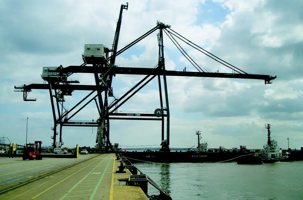
Cranes with a greater height and outreach are often seen as a necessity to accommodate the latest and future generations of containerships. Indeed, the largest container vessels typically have a depth from deck to keel of 25 metres, with some new tonnage reaching 27 metres. When calling at a port not fully loaded, such vessels can come in 5.5 metres above the Plimsoll line. What’s more, the 9’6″ high-cube container is becoming predominant compared to the traditional 8’6″ high unit.
“New 8,500 TEU ships have eight stacks of up to 9’6″ in front of the bridge compared to six not so long ago, ” says Derek Smith, business development manager of Southampton Container Terminals (SCT). “So there is potentially another two boxes plus another 8ft, meaning vessels in excess of 20ft higher than they were only a few years ago.”
So should container terminals rush out and order new quay cranes?
Well, no. The expense of new cranes may be unnecessary. Modifying existing quay cranes to gain additional height and outreach may well be a viable alternative, even if you think your cranes are too old.
Increasing crane height and outreach by up to ten metres can be easily achieved in many cases, provided the crane is structurally sound. When you consider that ten metres in height equates to three boxes, it is clear what a massive difference this can make to any terminal. Furthermore, including additional renovation measures in the project can breathe new life into old equipment.
SCT has recently completed a project to raise the height of five 1993 built Morris ship-to-shore cranes by five metres to 35 metres. “With a 30 metre crane, when you get to high water with a six-high stow for example, to get access to boxes on the other side you have to peel off the whole deck of the sixth tier and possibly even the fifth tier, ” says Smith. “We were restricted to putting the high profile vessels on berths 206 and 207 – our deeper draught berths with the bigger cranes.”
SCT awarded the contract to Bath-based Seward Wyon which developed an innovative jacking system to lift the cranes. With this system, the cranes drive over the top of the assembly so it can be left in one place and the cranes can be moved over it on their own rails.
PLANNING PERFECTION “It takes up about 100 metres of quay space with the jack in one position and the crane being prepared alongside it, ” says Smith.
“Although this doesn’t severely disrupt operations, it does impact to a certain extent.” Organising downtime is a crucial element for any crane modification project but was a particularly interesting challenge at SCT because the cranes were being worked on in situ on the quay, rather than moving them out of line into a separate working area.
“Once you’ve got the crane fixed in position, you can’t move other cranes past it, ” explains Smith. “You have to make damn sure you have sufficient assets on both sides of the crane being worked on. We tried to keep three cranes available on 204 Berth at the end of the quay so we could use that as an overflow berth or four cranes accessible on 205 Berth. It is crucial that the berth is not disrupted by preventing other cranes or ships working and so we started with one of the middle cranes.”
The Seward Wyon jacking system has a 1,000 tonne lifting capacity and is capable of withstanding wind speeds of 80mph. “There are four gantry arrangements under the portal beams, ” explains Ken Cross, director of Seward Wyon. “Each is essentially a pair of tubes on the outside with a single tube on the inside which slides up to push the crane up using strand jacks which are attached to a frame at the bottom side of the centre tube. That pulls the tube up through a set of guides from a mid-height platform.”
The crane weight being jacked was about 800 tonnes without the lower sill beam and the bogies which stay on the ground. The joints for the new legs are just above the sill beam. The flanges were split on the legs and templates made of the hole-pattern to ensure that the holes in the flanges line up when new leg sections were inserted.
Because raising the cranes in this way causes them to be less stable, the crane was braced at the top portal section and the lower portal section so that it is less flexible. It has also been designed to enhance structural integrity sufficient to allow twin-lifting.
Elsewhere in the UK, Thamesport, operated by Hutchison, has also just completed a crane modification project but using a very different method. Evergreen had several new larger 8,000 TEU capacity vessels coming into service in May this year, each with containers stacked seven high on deck and 17 rows across.
“We wrote a relatively simple specification for modifying five 15 year old MGM cranes, ” explains Richard Coates, engineering manager at Thamesport. “The contractor was asked to put forward a design proposal that would increase the cranes’ height of lift by 3 metres and increase the outreach by 2.5 metres.”
Noell Kone Cranes was awarded the contract which, unlike SCT, did not involve cutting the legs and inserting new beams. Coates explains:
“Our MGM cranes had a particularly large trolley assembly which was very heavy and hung very low under the main trolley beam of the crane.
It had some anti-sway devices that were redundant and were never really used because they were unreliable.”
OUT OF THE BOX THINKING Kone and Thamesport engineers came up with a method whereby the trolley was replaced with a smaller more compact one. In this way the additional three metres in lifting height was achieved without cutting the crane legs.
“Kone supplied the new trolley and modified the rope sheave positions at the back-reach and boom tip, ” continues Coates. “The trolley was made shorter with integral buffers rather than external buffers, and that was how the 2.5 metres extra outreach was achieved.”
The project included adding braking on the trolleys. Because it is a rope driven trolley, if the ropes on the original design trolley were to break, the trolley could free wheel, so trolley brakes were included as a safety measure.
Modifications were also made to the access walkways for the drivers to get into the cabs. The cabs themselves were replaced with the ‘ErgoCab’ design from Dutch manufacturer, Merford. Coates adds: “The sheaves were all replaced as part of this project so, as well as the benefit of the extra height and outreach, most of the moving parts have been replaced.
“All the headblocks have been replaced and there is less sway with the modified sheave arrangement. To get anti-sway on the older cranes, the rope angles coming up from the spreader went up in a Vshape, which could cause problems and damage going down ships’ cell guides. With the new headblock, the anti-sway is done with the sheave mechanism on the headblock, so the ropes are a lot more vertical on the cranes, which should reduce damage to hoist ropes.
We previously had dampers on each corner of the headblock to reduce sway and, as the dampers wore and their characteristics changed, the sway of the spreader would change. That’s another problem we’ve managed to sort out.”
Organising downtime to complete the project at Thamesport presented it own range of issues. The jetty length at Thamesport is 655 metres with a total complement of six cranes, five of which needed modifying.
“Being a two-berth jetty, it is very difficult to take cranes out of service, ” says Coates. “Taking out one of the middle ones would have been particularly problematic to operations. So we decided to modify the two end cranes, move them into a central position and then move two others to the outer edges. So the crane that was out for modification was always an end crane. We allowed, within the terms of the contact, a 50 metre working area at either end of the jetty when they were working on that specific crane.”
Kone used its own system called Fluid TS, which involves jacking the crane with load modules that are then moved along a slideway on a bed of nitrogen, therefore moving the crane from the jetty to barge and vice versa. Because the Fluid TS system was owned by Kone and was available, the movement of the cranes was particularly cost effective compared to the hire of a multi bogie drive unit.
“The availability of this system is where they got a lot of their cost benefits” says Coates. “We took the crane off of the jetty onto the barge on one high tide and left it there overnight and on the next day’s high tide, we brought it back on again. Each crane was worked on for a period of four to four and a half weeks and, when it was complete, it was moved along onto the jetty and another one was repositioned to the working area.”
This method ensured minimal impact on operations and the terminal was able to sustain five-cranes working all the time and maintain two berths without adversely affecting productivity.
“We were fortunate that we managed to find a way to achieve what we wanted without any major structural work, ” says Coates.
“My advice to other terminals is to evaluate every possibility in achieving more height and outreach before resolving to take burning gear to the legs of the crane.”
SCT’s Derek Smith concludes: “Bite the bullet as soon as you can and get it done. We wish we’d done it earlier.”
Related Articles
 CONTAINER & CARGO HANDLING
 CONTAINER & CARGO HANDLING